
 Authorized Dealer
 English
 中文
中文 日本語
日本語






As fundamental electronic components, bridge rectifiers are widely utilized in various power supply equipment. During operation, they inevitably generate a certain amount of power dissipation. Inadequate thermal management can severely compromise their reliability and operational lifespan. Shenzhen World Industrial Co., Ltd. has conducted in-depth research into the performance of bridge rectifiers under different thermal solutions. By systematically analyzing their thermal mechanisms and revealing the thermal resistance characteristics ( RθJA / RθJC ), we provide critical guidelines for power supply designers to select the optimal bridge rectifiers.
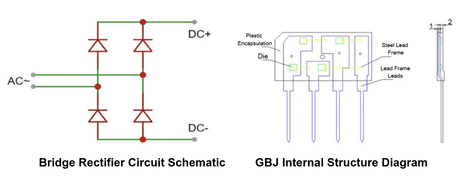
Internally, a bridge rectifier consists of a bridge circuit composed of four diodes, designed to convert the input alternating current (AC) voltage into a direct current (DC) output.
I. Thermal Resistance Comparison: Significant Effectiveness of Built-in Heatsinks
Thermal resistance ( RθJA , junction-to-ambient thermal resistance) is a core parameter for evaluating the thermal dissipation efficiency of a device. The following comparison illustrates the total junction-to-ambient thermal resistance of GBJ bridge rectifiers with and without built-in heatsinks:

Data indicates that for GBJ bridge rectifiers integrated with a built-in heatsink, the RθJA value decreases from 36.6℃/W to 36.1℃/W, demonstrating that the built-in heatsink effectively enhances overall thermal dissipation efficiency.
II. Empirical Data Validation
Static Test Data:

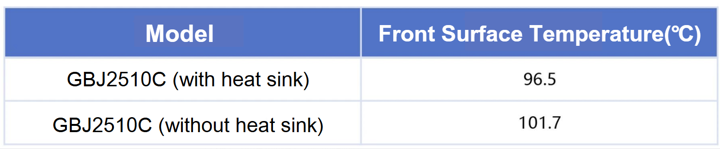
The front-surface temperature of the model equipped with a heatsink is approximately 5℃ lower than that of the model without a heatsink. This visually demonstrates the practical effectiveness of built-in heatsinks in suppressing temperature rise and optimizing thermal management.
III. Thermal Path Analysis: Lead-Primary and Package-Secondary Heat Dissipation
Thermal Path Analysis, Lead-Primary and Package-Secondary Heat Dissipation:
1.Thermal resistance from leads to PCB: approx. 60.52℃/W (Primary thermal path)2.Thermal resistance from package surface to ambient air: approx. 92.62℃/W (Secondary thermal path)
Therefore, in natural convection cooling designs, optimizing the copper area of the PCB pads is the key to enhancing thermal dissipation capabilities.
If an external heatsink combined with forced air cooling is adopted, the total system thermal resistance can be further reduced to 6.43℃/W, making it highly suitable for medium-to-high power applications.
IV. Practical Application Recommendations
Based on empirical testing and analysis, we provide the following recommendations for power supply design engineers:
- Prioritize Models with Built-in Heatsinks
In applications where space permits or thermal conditions are constrained, it is recommended to select models integrated with built-in heatsinks, such as Shenzhen World Industrial Co., Ltd.'s GBJ2510C. This helps lower the operating junction temperature and enhances overall system reliability. - Focus on the Thermal Resistance Parameter (Rja)
is one of the critical metrics for component selection. A lower RθJA value indicates that the device will experience a lower temperature rise under the same power dissipation, or it can handle higher power under the same temperature rise limitation. - Optimize External Thermal Design
Even when selecting models with built-in heatsinks, it is still necessary to pair them with external heatsinks or optimize the PCB copper foil layout based on actual power dissipation and temperature rise requirements to achieve optimal system-level thermal management. - Ensure Installation and Thermal Coupling Quality
The installation method of the bridge rectifier (e.g., screw torque/pressure and the application of thermal grease) significantly impacts the final thermal performance. It is crucial to ensure excellent thermal contact.